Hot Dog Demonstration
Two terminals of a wire were connected to metal probes on a stand and a hot dog was placed between them. Five LED's were placed on them with different orientations with respect to the hot dog. Some were placed with their terminals parallel to the hot dog while others were placed perpendicular. Also, some of the LED terminals were stretched out while others remained close to each other.
The purpose of this demonstration was to see the behavior of current flow. When plugged in, some lights lit up either brightly, dimly, or didn't light up at all. Looking at this like a circuit, the LED's that lit up were the ones that were wired in series while the ones that did not light up were wired in parallel.
When plugged in, the terminals provide a potential difference lengthwise along the hot dog. The LED's that were in parallel (perpendicular to the hot dog) did not light up because there is no potential difference between the two leads since they both are anchored on the same cross section. The ones in series, however, did light up because there are potential differences between different hot dog cross sections. This also means that the farther the leads are connected in series, means that the more potential there will be, thus the brighter the LED will light up.
Dusk-to-Dawn Light
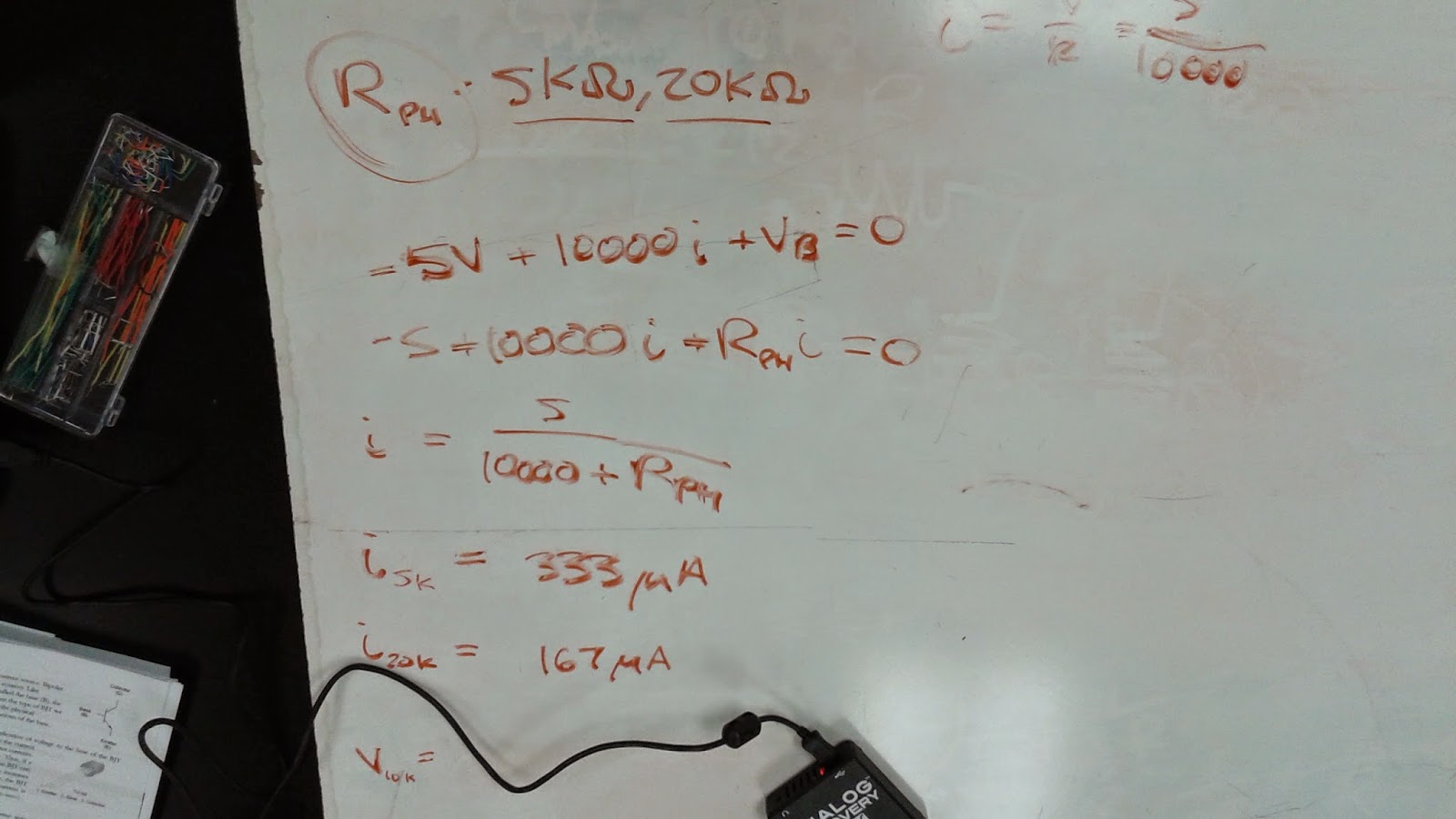
In this lab we wire a circuit that will have a light turn on when the ambient light is dark and turn off when the ambient light is bright. This behaves like a security light that many homes have that turn on after sunset and turn off in the morning. We use a 5 V source connected to a Bipolar Junction Transistor (BJT - 2N3904). Voltage is divided through a 10 kΩ resistor and a variable photocell resistor. The resistance of the photocell increases as the ambient light becomes darker. This increase in resistance creates a larger potential difference between the base of the transistor and ground, which also means that more current will flow into the base terminal of the transistor. When the threshold current of the transistor is met or surpassed it becomes active, which means that current is then able to flow into the collector terminal and thus flow through the Light Emitting Diode (LED), turning the light "on".
If we apply KVL through the outside loop, we get an equation for current in terms of resistance of the photocell. Plugging in the values 5 kΩ and 20 kΩ for this resistance, we get the two corresponding currents 333 μA and 167 μA, respectively.
The measured resistance of our 10 kΩ was 9.89 kΩ.
When we covered the photocell, the resistance increased to 144.1 kΩ.
These are our measured values for the voltages across the photocell (V_B) and LED (V_D). When there is dark ambient light, both the voltages across the photocell and LED increase greatly. We are more concerned with the voltage increasing across the LED because it is what makes it light up. We also note that under bright ("light") ambient lighting, the voltage is significantly lower in both circuit elements.
This shows the LED lighting up as the photocell is surrounded by the shade of a hand.
Finally, we can see the Dawn-To-Dusk light in action in this video.


No comments:
Post a Comment